Thursday, July 3, 2014

Final assembly Phase 2

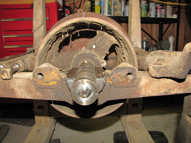
I am now completing the final steps for the shaft axial retainers and radial bearing. I greased the bearings and tightened the bearing caps. During cleaning of the grease cup I noticed that it holds a 1893 patent mark. This would indicate the possible age of the machine. The machine also has two other patent marks. One on the bed stone that reads 1870 and one on the grease cap that reads 1889. My guess is that the machine was built after 1893.

Sunday, June 29, 2014

Final Assembly Phase 1

Today, I began to form the main shaft seal. This seal keeps ground cornmeal inside the main housing during operation.

The seal material is leather and is about .25 inches thick.
It seals around the outside of the inboard bearing housing
It is retained by 4 screws and a cover plate.
 I also fit the main shroud that encloses the runner stone. 

Sunday, April 20, 2014

Easter weekend

This weekend I logged some hours on the grist mill. Finishing cross drilling at the posts and installing structural fasteners for the wooden frame. Also I continued painting and polishing various components. One of which is the burnishing of the runners stone and shaft.

I used a technique of working a wire brush driven by a die grinder and then followed by an application of olive oil and then more burnishing with the die grinder and wire brush. This result in a food grade finish that will prevent rust. It removed significant quantities of dust and debris from the runner stone assembly.

Furthermore,  I found lead balance weights on the backside of the runner stone. In a earlier operation, performed by Roger and Jeff the front side of this wheel was filled with hydraulic concrete or mortar to fill voids between the banding and the stone there by increasing the reliability and rigidity of the runner stone assembly. Next week, I will push for completion by the time of the open house April 27th at Anderson Mill and Muesum. I will probably bring it to the open house regardless, for show and tell.

Sunday, April 6, 2014

The pour

On March 27th 2014 Jeff Campbell, Roger Shull and Julia Land met in my garage for the babbit bearing pour. Jeff loaned us his turkey frying propane stove and Roger loaned us his cast iron pot to melt the babbit. This set up worked very well for melting the babbit. It only took about 15 minutes for it to be completely molten. Meanwhile, I used a torch to heat the frame of the gristmill in the region of the bearing journal.


I did the pour and the bearing filled up. I used a clay for damming up the ends of the journal to keep the babbit from running out. The clay and babbit did have an undesirable interaction but the effect was minimal and limited to some minor bubbling at each end of the bearing.

Monday, March 24, 2014

Setting up for Babbit Bearing Pour

I built this temporary frame to position the primary shaft including the runner stone which will center the bearing and main shaft with respect to the frame. I'm using the upper bearing caps on both out board and inboard bearings to position the shaft accurately and then I built this V block stub shaft support near the end of the frame

Wednesday, December 25, 2013

Christmas 2013 Progress Update

The new native Pecan wooden frame has been shellacked. Also the fasteners were wire brushed and hand filed to remove rust then painted black

Here is a close up of the installed fasteners.


And here it is with the Hopper installed.


Saturday, November 16, 2013

Fall Progress Update

Recently, Jeff Campbell has completed the task of fabricating all new wood components for the mill. Here are a few of the images. Link to Jeff's images We chose native Texas pecan as a replacement wood. There was much speculation about the species of the original wood but no clear determination was made. Pecan is a good choice for this application in my opinion. It is hard enough to be used as a structural member and will also have a beautiful appearance.

Diversified Machining in Bertram, Texas is repairing many of the damaged parts. They have removed a pulley that was stuck on the main shaft. and are preparing to weld the cracked main frame and pour new babbit bearings.

Wednesday, June 12, 2013

The Metal Frame is Cracked!

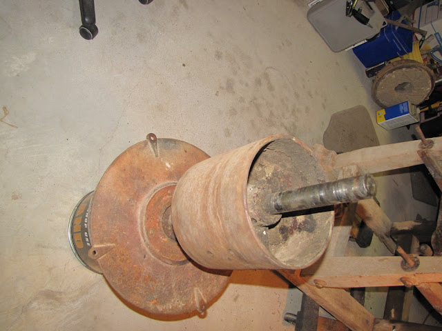
After removing the bearing caps, I was able to remove the main shaft from the frame. The shaft at this point  includes three major components. The main drive pulley, the seal housing and rear main stone housing end plate as well as the runner stone and it's enclosure.


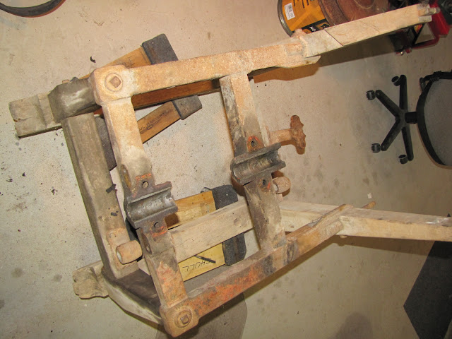
 Once this large subassembly is removed from the mill what is left is the mill's metal frame and the mill's wooden frame.


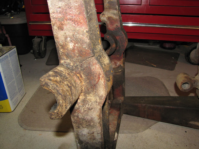
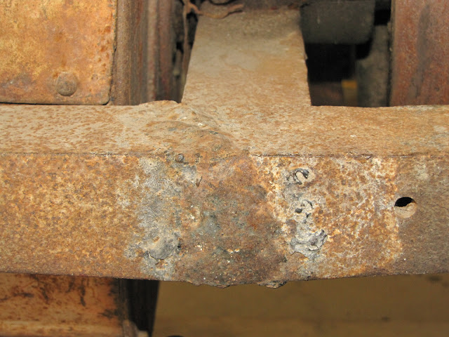
Upon close inspection of the metal frame I found a large crack adjacent to the inboard or central radial bearing seat. This will need to be repaired. It is probable that it was overlooked when the frame was repaired previously.

Sunday, June 9, 2013

Main Journal Bearing Disassembly

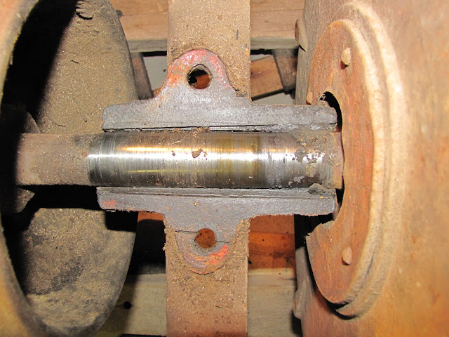
More recently I have been taking apart the main shaft bearings. The inboard bearing is located between the pulley and the runner stone on the center frame support. Shown below with bearing cap removed


Here is a shot of the bearing cap. Shaft looks ok and can still be used without any repairs so far.


Next I moved to the adjustment wheel section located at the end of the main shaft. This region includes the stone gap adjustment knob, thrust bearing and grease cup, main thrust spring and radial bearing assembly. Shown below with adjustment knob assembly and axial retainer bolts removed.


Here is what it looks like with the thrust bearing housing, main spring and spring retainer removed.


and after removing the radial bearing cap it looks like this.


Tear Down and Clean Up

I have spent the last few sessions disassembling the mill. I photograph everything as I go so I can remember how to put everything back together. With the mill sitting on two furniture dollies I rotated the mill and photographed every detail in the assembled state from lots of different angles. Next, I began removing the larger accessory items like the grain hopper and feed chute.


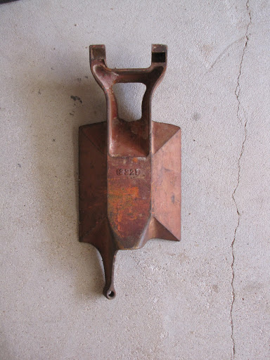
Once I have them off the mill I take snap shots of the piece from all angles looking to capture specific details or damage. For instance, here is the bottom of the feed chute. With what I believe is the part number for the chute


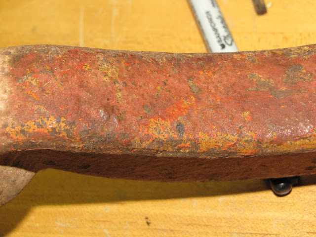
After a complete photo documentation, I make some handwritten notes in a log book especially if there are damaged feature or interesting items worth recording. Below I am trying to determine exactly what the original color was. There appear to be two coats of paint. One thin yellow layer similar to caterpillar yellow and one thick heavy top layer similar to Massey Ferguson Red.


While disassembling the Bedstone Support Bearing I found a aftermarket component added to the upper bearing clamp assembly. It is a pipe fitting. It was placed under the bearing cap presumably to take up slack space in the clamp. I think there may have been a spring here originally pushing down in the upper spherical bearing journal insert.


Below is an image of the inboard face of the bedstone. It looks to be in good condition. The bedston is missing a steel perimeter hoop. I am guessing this type of bedstone mounting arrangement was deployed to allow the bedstone to tilt on the ear features located at 3 and 9 o'clock. Perhaps this would allow the stone to align more precisely with the runner stone.


The next image is of the inboard face of the runner stone. Also of note, is the grain auger, Bedstone mounting tabs, and the flour exit chute opening located in the main housing sheet metal.. The runner stone has a very large chip missing from one corner. This may require replacing the stone.


Thursday, June 6, 2013

Miss Minnie's Mill Restoration Begins

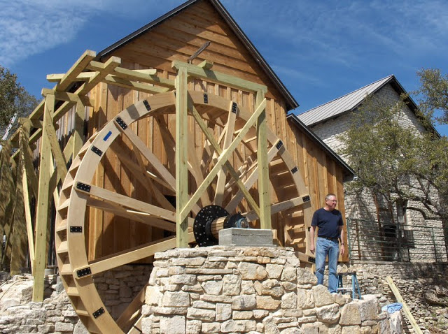
Last week, I started the restoration of a 14" Nordyke and Marmon Stone Buhr Mill. This mill belongs to the Anderson Mill Garden Club. Since I was elected chairman of the Memorial Board last year, I have been involved in a number of restoration projects for the club. The first was the replacement of the 16 foot water wheel seen here. Our intent is to connect the Nordyke mill to this waterwheel eventually using it to grind corn for our scholarship program.

The age of the Nordyke Mill is not known to me. It has a patent date of August 1st, 1870. It is the smallest of the three shown here in this catalog page ~1920. It came with a additional feature called a bolter that was used to sift the ground grain.


It ran at about 1000 RPM according to this document. and needed ~3hp at that speed. We think it was powered by a 6HP 450 RPM Fairbanks Morse Flywheel Engine that is being restored by Alan Null at Diversified Machining in Bertram, Texas.

The link below will take you to the Picasa Image Archive for this project.

The mill was in remarkably good condition for its age. Minnie Anderson used this mill presumably to grind corn between 1923 and 1945. It was fitted with a homemade hopper extension that allowed the operator to load a larger amount of grain. 


It is also a "mostly" complete assembly. The only missing part I have noticed is the sifter/bolter attachment. Hopefully, I can talk my friend into making a replacement.

There was some damage and a subsequent repair to the main steel support frame. This weld repair appears on both sides of the frame.


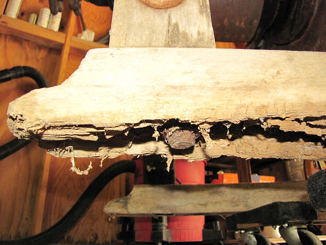
Additionally, the wooden skids that contact the floor had significant insect damage and were rotten. One of the short corner posts was completely detached from the floor skid member.